


BMS Safety Starts with the Right MOSFET Selection
2026-03-30
BMS: The Cornerstone of Safety and Efficiency – Optimal MOSFET Selection for Pre-Charge & Main Relay Drive Circuits
Foreword: MOSFET Selection Defines the Lifeline of BMS Core Circuits
In power battery systems such as electric vehicles and energy storage systems, the Battery Management System (BMS) serves as the central hub for ensuring safety and controlling energy flow.
Among its most critical functional blocks, the pre-charge circuit and the main relay drive circuit play essential roles in high-voltage power-on and system switching.
MOSFETs, as the core switching devices in these circuits, directly impact system safety, operating efficiency, and overall lifespan. Improper selection can lead to excessive losses, unstable operation, and serious risks such as thermal runaway, relay adhesion, or battery damage.
With extensive experience in power semiconductor design, Goford focuses on these high-risk BMS applications, providing optimized MOSFET solutions tailored to real operating conditions.
1. Two Key BMS Circuits and Their Roles
1.1 Pre-Charge Circuit: The Safety Buffer
At system startup, the DC bus capacitor initially has zero voltage. Direct connection to the battery can create a large inrush current, potentially damaging capacitors, battery cells, and downstream components.
The pre-charge circuit limits this current by gradually increasing voltage, acting as a buffer during power-on.
The MOSFET in this circuit must:
· Handle high transient pulse currents
· Switch quickly and reliably
· Maintain stability under extreme conditions
It serves as the first line of defense in the system.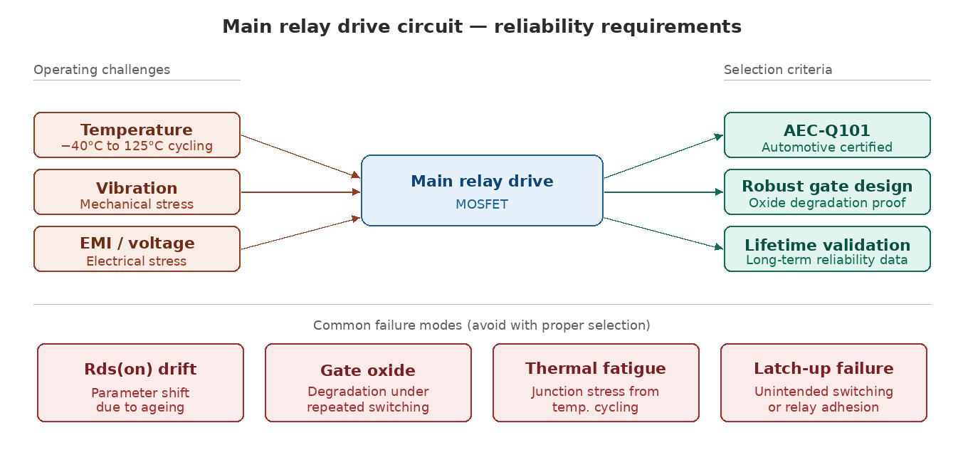
1.2 Main Relay Drive Circuit: The Power Gatekeeper
The main relay drive circuit controls the system throughout its lifecycle, including start/stop operations, charging/discharging, and fault protection.
The MOSFET here must:
· Operate continuously and reliably
· Withstand harsh environments (temperature, vibration, voltage fluctuations)
· Prevent malfunction such as unintended switching or relay sticking
This circuit ensures continuous and safe system operation.
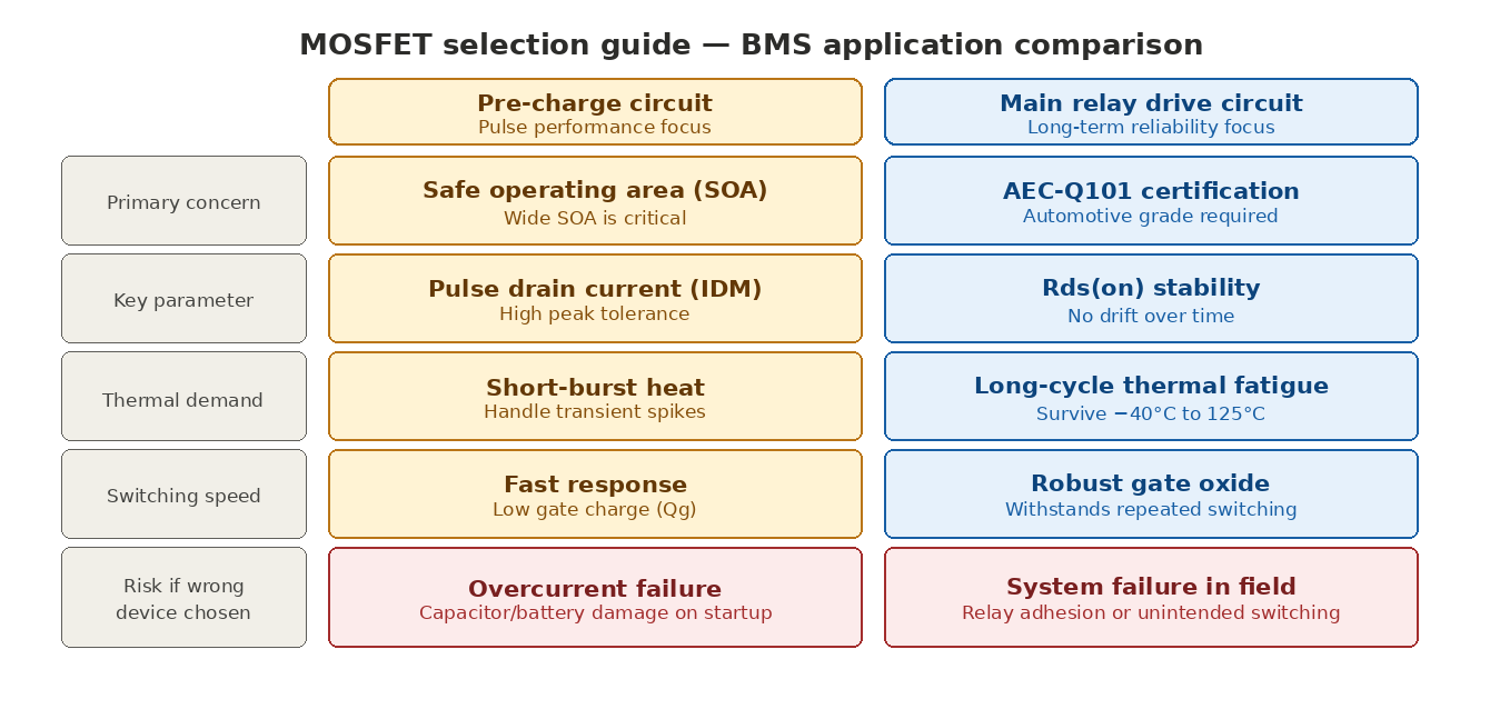
1.3 Key Differences in Requirements
Scenario | Key Focus |
Pre-Charge | Pulse capability & SOA |
Main Drive | Reliability & durability |
Recognizing these differences is essential for proper device selection.
2. Pre-Charge MOSFET Selection: Focus on SOA
2.1 Key Performance Requirements
· High pulse current capability
· Wide Safe Operating Area (SOA)
· Fast switching speed
· Low Rds(on) to minimize losses
2.2 Common Issues with Standard MOSFETs
Many general-purpose MOSFETs suffer from limited SOA and poor pulse tolerance. Under high inrush conditions, they may fail due to overheating or breakdown.
These failures are a major cause of:
· Power-on instability
· Early product failures
· Increased development time
2.3 Recommended Selection Strategy
Engineers should prioritize:
· Pulse drain current (IDM)
· SOA characteristics
· Thermal performance
· Gate charge
Wide SOA is the most critical factor for pre-charge reliability.
3. Main Drive MOSFET Selection: Reliability First
3.1 Operating Challenges
· Temperature cycling from −40°C to 125°C
· Mechanical vibration
· Electrical stress and EMI
3.2 Common Failure Modes
· Rds(on) drift due to aging
· Gate oxide degradation
· Thermal fatigue
· Latch-up failure
3.3 Recommended Selection Criteria
Selection should prioritize:
· AEC-Q101 certification
· Proven reliability data
· Robust gate design
· Long-term lifetime validation
Parameter comparison alone is not sufficient—reliability must come first.
4. Goford Scenario-Specific MOSFET Solutions
To address the different requirements of pre-charge and main relay drive circuits, Goford provides application-oriented MOSFET solutions that balance safety, efficiency, and long-term reliability.
· Pre-charge applications: Optimized for stable high-voltage startup and effective inrush current control.
· Main drive applications: Designed to ensure consistent performance and reliability throughout the system lifecycle under harsh operating conditions.
By aligning device characteristics with real application needs, Goford helps customers achieve more robust and efficient BMS designs.
5. Conclusion
MOSFET selection in BMS systems is a balance between:
· Pulse performance (pre-charge)
· Long-term reliability (main drive)
Choosing the right device improves system safety, reduces failure rates, and extends battery lifespan.
As battery systems evolve toward higher voltage and higher power density, precise MOSFET selection becomes increasingly critical. Goford continues to deliver application-driven, high-reliability solutions to support next-generation BMS systems.
 Latest news
-
2026-06-24
Energy Security Rises: Why BESS Is Now a Core Pillar of the Power System
-
2026-03-30
BMS Safety Starts with the Right MOSFET Selection
-
2026-03-30
N-Channel vs P-Channel MOSFETs in BMS: Which One Belongs Where?
-
2026-03-05
MOSFET Thermal Design and Reliability in BMS Systems
-
2025-12-25
Goford 150V P-MOSFETs: Ultra-Low RDS(on) for High-Power Apps